ICARELIFE — Technical Guide
Lead Sheet Radiation Shielding: Installation Method for Ceilings and Walls
For contractors, hospital consultants and project teams building X-ray, CT and radiotherapy rooms. Covers the steel frame build-up, how lead sheet is fixed, and the barium sulfate plaster method for masonry walls.
Quick Answer
- Lead sheet radiation shielding is fixed to a welded steel frame, boarded, then bonded with contact adhesive.
- Main joists are 80 × 40 mm channel steel; secondary and edge joists are 80 × 40 mm angle steel.
- Barium sulfate plaster is the alternative for masonry walls: mixed 4:1 with ordinary cement, in 1.5 mm coats.
- Shielding thickness is set by the project's radiation physicist, not by the installer.
What Lead Sheet Radiation Shielding Is
A shielded room is a closed box: walls, ceiling and floor all carry a barrier, and every opening in that barrier is dealt with. Lead sheet is the barrier in the build-up below.
The barrier is not structural. It is a thin layer of lead carried on a frame, protected by a board, and finished with a decorative surface. What makes it work on site is the order of the layers and where the fixings land.
Shielding layer
Lead sheet, or barium sulfate plaster where the wall is masonry or concrete.
Steel frame
Welded joist grid that carries the boards and the lead, anchored to slab and walls.
Backing board
Fixed to the frame before the lead, giving it a continuous face to bond to.
Decorative finish
ACP panel, emulsion paint or another ceiling finish applied over the shielding.
Two system types are covered here. The ceiling is a flat suspended build-up with lead sheet installed on it, door panels reinforced, and the assembly closed with gypsum board on the outside. The framing for it is steel joist construction throughout.

Preparation and Setting Out a Lead Sheet Radiation Shielding System
Most shielding defects are set before the first sheet goes up: wrong level, wrong grid, or an opening nobody checked.
Materials and sections
| Component | Section / type | Role |
|---|---|---|
| Lead sheet | Rolled sheet, cut to grid module | The shielding layer itself |
| Main joists | 80 × 40 mm channel steel | Primary spans between anchors |
| Secondary joists | 80 × 40 mm angle steel | Cross-bracing, carries board edges |
| Edge joists | 80 × 40 mm angle steel | Perimeter trim at walls |
| Anchors | 12 × 15 expansion bolts | Fixes frame to slab and wall |
| Adhesive | Contact adhesive | Bonds lead sheet to the backing board |

Tools on site: rotary hammer, arc welder, hand-held cutting saw and cutting machine. Technical preparation means the drawings reviewed, method statement issued, main-joist routing and grid layout drawn, construction sequence and joint details agreed, and the crew briefed before work starts.
Lead sheet reaches the room as wrapped rolls, strapped bundles and palletised stacks.


Setting out, in the order it has to happen
- Clear the space
Remove obstacles from the ceiling and the surrounding area before any drilling.
- Check the openings
HVAC ducts, plumbing, fire services, access hatches and electrical routes — each one is a penetration in the barrier.
- Square the room
The four corners of the ceiling must be square; a room that runs out of square shows at the edge joists.
- Set the level datum
Benchmark points at the design elevation, taken to every wall.
- Mark symmetric cross lines
On ceiling and wall base faces, so the grid is balanced from the centre out.
- Strike the joist grid
Horizontal and vertical lines at joist spacing. These are the connector fixing points — expansion bolt or shot pin positions.

Installing Lead Sheet Radiation Shielding: Key Points
The build-up is welded, coated, boarded, painted, then bonded. Each step closes over the one before it, so the sequence is not optional.
Work sequence
- Weld the steel frame
Edge joists and main joists hung on one level plane, secondary joists inserted last.
- Anti-rust treatment
Weld areas and cut ends treated before anything covers them.
- Cut and fix the backing board
Board continuity is what the lead relies on.
- Apply fireproof coating
On the frame, before the decorative layers close in.
- Bond the lead sheet
Contact adhesive, sheet by sheet, laid in sequence and pressed flat.
- Fabricate and fix decorative joists
The framing that carries the finish over the lead.
- Patch openings cut during lead work
Every hole made in the sheet is closed with the same material, overlapped.
- Decorative finish
Emulsion paint or another ceiling finish, by the client's finishing trade.
Fix the lead sheets in order, one after the next, directly to the steel joists. When the decorative panels go on, use an auxiliary support to press the panel up against the joists while it is fixed. Once the lead is complete, the ceiling can be finished directly.
Barium Sulfate Shielding Material
Where the wall is masonry or concrete and a plastered barrier is simpler than a framed one, barium sulfate does the same job in render form.
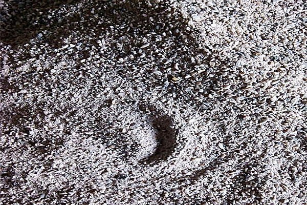
Barium sulfate is chemically inert and stable, resistant to acids and alkalis, dense, with moderate hardness, high specific gravity and high whiteness. It absorbs harmful radiation — X-ray and gamma — and is non-magnetic and non-toxic. The material has a glassy lustre and an all-natural barite formulation.
It is used for interior and exterior wall finishing where X-ray and gamma shielding is required, and blocks radiation leakage. Typical applications are dental clinics, hospital X-ray rooms and CT rooms, radiotherapy rooms, and industrial NDT rooms.
The sand and the shielding coating are blended from granular and powder components in set proportions. Mixed with cement, the material is plastered onto walls.
Barium Sulfate Application Method
Four numbers govern this method. Get them wrong and the layer either sags, cracks, or cures before it is on the wall.
| Parameter | Value in this method | Why it matters |
|---|---|---|
| Mix ratio | Shielding material : ordinary cement = 4 : 1 | Adjusted for local temperature and humidity |
| Coat thickness | About 1.5 mm per coat | Thicker coats sag and pull off the wall |
| Working life | Within 3 hours of mixing | Mixed material is used as the work proceeds |
| Minimum room temperature | 10 °C in winter, with anti-freeze admixture | Below this the render will not cure properly |
Preparation before the first coat
Spray the wall lightly with water so the render bonds to it. Set thickness reference points on the wall with the shielding material, so the layer stays uniform. Render thickness itself is set by the hospital department the room serves — that is a design decision, not a site one.
Applying the render
- Mix to the process ratio
Only as much as the work pace needs, used as you go.
- Apply 1.5 mm coats
No build-up in one pass; the second coat goes on after the first has set.
- Scarify the joints
Roughen a battered overlap at each construction joint, or the joint cracks.
- Repair cracks during curing
Cut a 10–15 mm groove along the crack to the bonded layer, fill level with shielding mortar.
- Trowel the sealing coat
A cement-plaster finish over the completed wall closes the surface and protects the layer.
Quality control
Use the mix within three hours of mixing, and mix strictly to the stated ratio. After the perimeter walls of the machine room are finished, apply the cement-plaster sealing coat. Supervision stays with the applicators and the QC inspector — the method only works if it is actually followed.
Terminology Used in This Guide
The terms that decide what gets built and what gets checked. Where a supplier or local code uses a different word for the same thing, this is what the method means.
| Term | Meaning in this method |
|---|---|
| Lead sheet | Rolled lead installed as the shielding layer on ceilings, walls and door frames; supplied in rolls and cut to the grid module on site. |
| Lead equivalence (mm Pb) | The thickness of lead that attenuates radiation by the same amount as the barrier actually built — the unit a room is specified and surveyed in. |
| Steel joist (keel) frame | The frame that carries the build-up: main joists span between anchors, secondary joists cross them, edge joists run the perimeter. |
| Channel steel / angle steel | Channel is a C-section (80 × 40 mm main joists here); angle is an L-section (secondary and edge joists). |
| Expansion bolt / shot pin | Mechanical fixings into concrete or masonry. Expansion bolts are drilled and torque-set; shot pins are powder-actuated. |
| Setting out | Marking the level datum and joist grid before drilling, so every anchor lands on a line instead of by eye. |
| Backing board | The board fixed to the frame before the lead, giving it a continuous face and closing the cavity. |
| Contact adhesive | Applied to both board and lead, bonded on contact — no clamping time, which is why it works overhead. |
| Fireproof coating | Fire-retardant coating on the welded frame, after anti-rust treatment and before boarding. |
| ACP panel | Aluminium composite panel — two aluminium skins on a mineral or polyethylene core; the decorative facing in the wall section above. |
| Barium sulfate (BaSO4) / barite | Dense, chemically inert mineral used as the aggregate in shielding plaster. Barite is the natural ore. |
| Shielding mortar | Barium sulfate sand mixed with ordinary cement (4 : 1 here), applied in thin coats on masonry or concrete walls. |
| Sealing coat | The troweled cement finish over the shielding render, closing the surface and protecting the layer. |
| Scarifying | Roughening the face of a stopped joint so the next coat keys in rather than cracking along the line. |
| Machine room | The X-ray, CT or radiotherapy room; its walls, ceiling and floor form the shielded enclosure. |
| NDT room | Non-destructive testing room — industrial radiography needs the same shielding as a medical room. |
| Access opening | The maintenance hatch into the ceiling void; checked at setting-out because it becomes a penetration in the barrier. |
Frequently Asked Questions
Thickness is specified as lead equivalence and is set by the project's radiation protection physicist or consultant, from the equipment workload, the room's occupancy factors and the local regulations that apply. It is not an installer decision and it varies from room to room in the same hospital. This guide covers how the barrier is built, not how thick it must be.
For masonry and concrete walls, often yes — the plaster is applied in thin coats and finished with a sealing coat. For suspended ceilings and drywall build-ups, lead sheet is the practical choice because the barrier has to be carried on a light frame. The two are also used together: plaster on the walls, lead on the ceiling. What must not change is the lead equivalence the physicist specified.
Four parts shielding material to one part ordinary cement, adjusted for local temperature and humidity. Each coat is about 1.5 mm, the mix is used within three hours, and winter work needs an anti-freeze admixture with the room held at 10 °C. Second coats go on only after the previous coat has set.
It depends on what is above and beside the room, which is why the physicist signs off each surface rather than the room as a whole. Where the ceiling does need shielding, the method in Part 1 applies: steel joist frame, backing board, lead sheet bonded to it, then the ceiling finish. The frame is sized for the added weight of the lead.
Every duct, conduit, hatch and door frame is a break in the barrier. Fix their positions at setting-out, before the grid is struck; overlap or sleeve the barrier at the opening; and patch any hole cut during lead work with the same material before the finish goes on. Openings moved after the lead is installed are the most common source of a failed radiation survey.
ICARELIFE — Room Envelope & Shielding
Need the shielding scope priced with the room package?
Send the room layout, the equipment list and the target lead equivalence. We will come back with the shielding build-up, the wall and ceiling package around it, and the interface points to your MEP scope — one quotation against one drawing set, instead of three suppliers meeting on site.