ICARELIFE — Installation Guide
Scrub Sink Installation Guide: Mounting Methods & Utility Requirements
Rough-in specifications, mounting selection, and the coordination checklist contractors need before the scrub sink arrives on site.
Quick Answer
- Scrub sink installation needs DN15 water inlets, a DN50 drain with trap, and 220 V power for sensor faucets.
- Wall-mounted units require solid brick or reinforced concrete walls — confirm before wall construction.
- Rough-in positions must follow the supplier's installation CAD drawing, not generic assumptions.
- Standard installs are contractor-executable with drawings, manual, and remote video guidance.
Choosing the Right Mounting Method
Mounting drives structural requirements — settle it during wall design, not at fit-out.
| Method | Description | Best For | Structural Requirement |
|---|---|---|---|
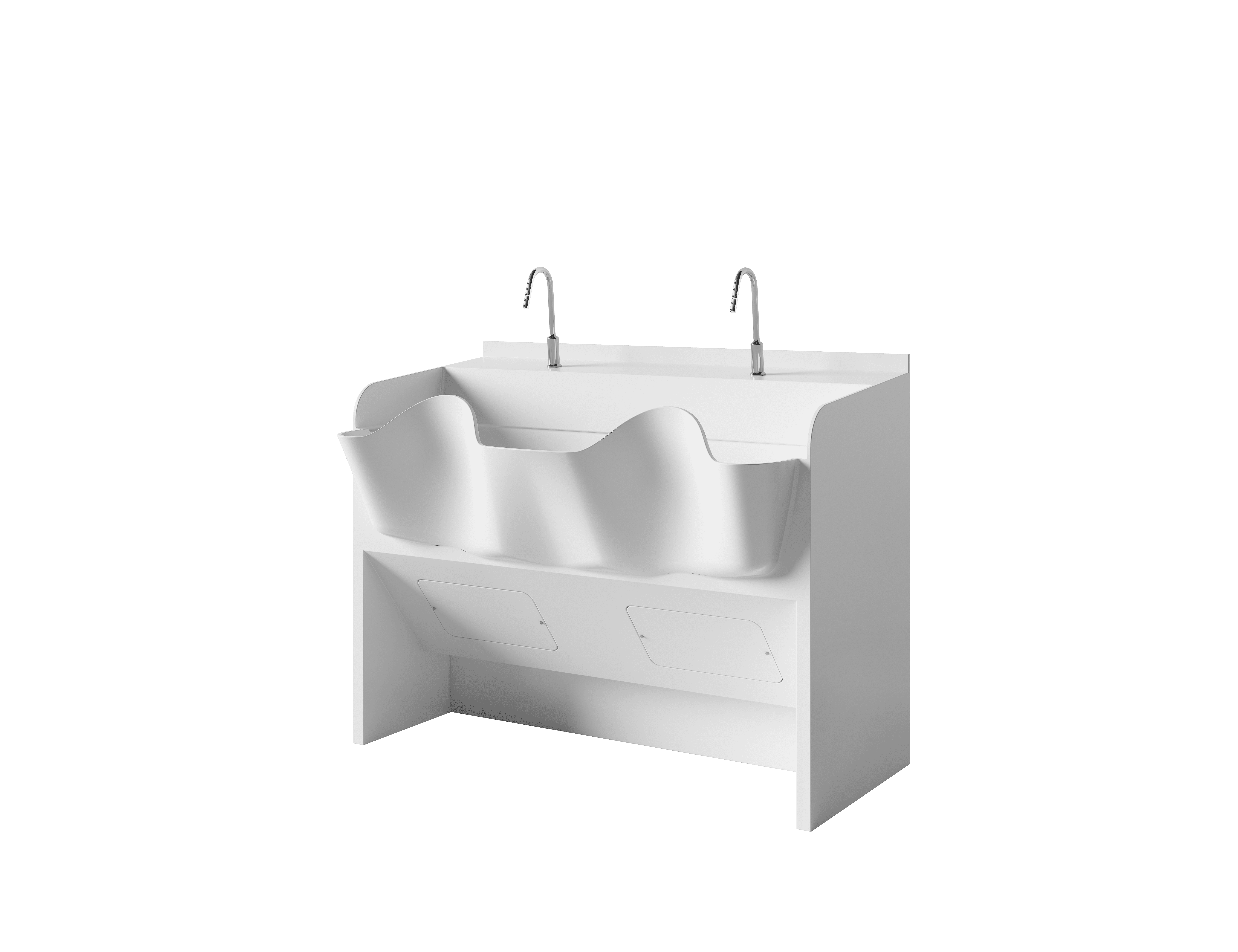
| Wall-mounted | Unit hung on wall; floor clear for cleaning | New OR builds (mainstream) | Solid brick or reinforced concrete wall |
| Floor-standing | Load carried to floor | Triple stations, retrofits | Reserved floor drain position |
| Cabinet type | Integrated storage cabinet below | Clinics, wards, public areas | Standard wall and floor fixing |
Utility Rough-In Requirements
Four connections, all positioned per the installation drawing before wall finishing.
| Utility | Specification | Notes |
|---|---|---|
| Cold water inlet | DN15 (1/2") threaded | Rear or bottom entry |
| Hot water inlet | DN15 (1/2") threaded | Where a hot faucet is configured |
| Drain | DN50 (2") outlet | Center-bottom or rear; trap recommended |
| Power (sensor faucet) | 220 V / 50 Hz, 10 A socket | Position per installation drawing; omit for manual faucets |
Pre-Installation Coordination Checklist
Six checks before the unit ships to site prevent nearly all installation delays.
-
1
Confirm wall structure matches mounting method
Solid wall verified for wall-mount; floor drain reserved for floor-standing units.
-
2
Set rough-in positions from the supplier CAD drawing
Water, drain, and power positions vary by model — never rough-in from a generic template.
-
3
Verify wall opening and clearance dimensions
Check unit footprint against final wall finishes, adjacent casework, and door swings.
-
4
Pressure-test water lines before closing walls
Leaks behind a sealed scrub sink are costly to access after cleanroom wall panels close.
-
5
Confirm power circuit for sensor faucets
Dedicated 10 A circuit, positioned per drawing, compliant with wet-zone electrical requirements.
-
6
Plan delivery access and protection
Confirm corridor and door clearances for the assembled unit; keep protective packaging on until final fit-out stage.
Installation Documents & Support to Expect from a Supplier
A standard install should not require a factory engineer on site — if the documentation is right.
A complete installation package includes a bilingual installation manual (PDF), an installation CAD drawing (DWG) with water and electrical positioning, and a wall-mount schematic that can be handed directly to the site contractor. With these documents, a competent contractor completes a standard installation without factory presence; remote video guidance covers questions during fit-out, and on-site engineer support remains available for complex or multi-unit projects by arrangement.
Solid Surface Maintenance & Scratch Repair Guide
Installation complete? Hand the facility team the maintenance schedule that protects the warranty and the surface.
ICARELIFE Technical Team
Healthcare infrastructure specialists with extensive experience in modular operating theaters, medical cleanrooms, and MEP system integration. ICARELIFE — Innovating Spaces That Heal.
Related Solutions from ICARELIFE
Continue the surgical scrub sink series.
ICARELIFE — Surgical Scrub Sinks
Planning the scrub area rough-in for your project?
Every ICARELIFE scrub sink ships with bilingual installation manuals, CAD drawings with utility positioning, and wall-mount schematics for your site team — plus remote video guidance during installation. Send your floor plan and our technical team will confirm rough-in positions for your coordination set.
ICARELIFE — Installation Guide
Scrub Sink Installation Guide: Mounting Methods & Utility Requirements
Rough-in specifications, mounting selection, and the coordination checklist contractors need before the scrub sink arrives on site.
Quick Answer
- Scrub sink installation needs DN15 water inlets, a DN50 drain with trap, and 220 V power for sensor faucets.
- Wall-mounted units require solid brick or reinforced concrete walls — confirm before wall construction.
- Rough-in positions must follow the supplier's installation CAD drawing, not generic assumptions.
- Standard installs are contractor-executable with drawings, manual, and remote video guidance.
Choosing the Right Mounting Method
Mounting drives structural requirements — settle it during wall design, not at fit-out.
| Method | Description | Best For | Structural Requirement |
|---|---|---|---|
| Wall-mounted | Unit hung on wall; floor clear for cleaning | New OR builds (mainstream) | Solid brick or reinforced concrete wall |
| Floor-standing | Load carried to floor | Triple stations, retrofits | Reserved floor drain position |
| Cabinet type | Integrated storage cabinet below | Clinics, wards, public areas | Standard wall and floor fixing |
Utility Rough-In Requirements
Four connections, all positioned per the installation drawing before wall finishing.
| Utility | Specification | Notes |
|---|---|---|
| Cold water inlet | DN15 (1/2") threaded | Rear or bottom entry |
| Hot water inlet | DN15 (1/2") threaded | Where a hot faucet is configured |
| Drain | DN50 (2") outlet | Center-bottom or rear; trap recommended |
| Power (sensor faucet) | 220 V / 50 Hz, 10 A socket | Position per installation drawing; omit for manual faucets |
Pre-Installation Coordination Checklist
Six checks before the unit ships to site prevent nearly all installation delays.
-
1
Confirm wall structure matches mounting method
Solid wall verified for wall-mount; floor drain reserved for floor-standing units.
-
2
Set rough-in positions from the supplier CAD drawing
Water, drain, and power positions vary by model — never rough-in from a generic template.
-
3
Verify wall opening and clearance dimensions
Check unit footprint against final wall finishes, adjacent casework, and door swings.
-
4
Pressure-test water lines before closing walls
Leaks behind a sealed scrub sink are costly to access after cleanroom wall panels close.
-
5
Confirm power circuit for sensor faucets
Dedicated 10 A circuit, positioned per drawing, compliant with wet-zone electrical requirements.
-
6
Plan delivery access and protection
Confirm corridor and door clearances for the assembled unit; keep protective packaging on until final fit-out stage.
Installation Documents & Support to Expect from a Supplier
A standard install should not require a factory engineer on site — if the documentation is right.
A complete installation package includes a bilingual installation manual (PDF), an installation CAD drawing (DWG) with water and electrical positioning, and a wall-mount schematic that can be handed directly to the site contractor. With these documents, a competent contractor completes a standard installation without factory presence; remote video guidance covers questions during fit-out, and on-site engineer support remains available for complex or multi-unit projects by arrangement.
Solid Surface Maintenance & Scratch Repair Guide
Installation complete? Hand the facility team the maintenance schedule that protects the warranty and the surface.
ICARELIFE Technical Team
Healthcare infrastructure specialists with extensive experience in modular operating theaters, medical cleanrooms, and MEP system integration. ICARELIFE — Innovating Spaces That Heal.
Related Solutions from ICARELIFE
Continue the surgical scrub sink series.
ICARELIFE — Surgical Scrub Sinks
Planning the scrub area rough-in for your project?
Every ICARELIFE scrub sink ships with bilingual installation manuals, CAD drawings with utility positioning, and wall-mount schematics for your site team — plus remote video guidance during installation. Send your floor plan and our technical team will confirm rough-in positions for your coordination set.